He had been told that you must do this with all single action revolvers. While that is true of MOST single action revolvers, it is not the case with the Ruger New Model guns (including the Vaquero, New Vaquero and New Bearcat).
The New Model Blackhawks have a transfer bar safety that was added in 1972 (the change from the original 3-screw to the New Models).
This lack of knowledge got me to thinking about how much I had learned after working on a couple of Ruger Vaqueros and an old model Blackhawk.
I thought I would share this with my readers....this post applies to the New Model Blackhawks and the Vaqueros.
These first two pictures are from the Ruger manual, it shows most of the parts and where they go.
We'll start with the Base Pin, besides the obvious (the axle for the cylinder), what is that spring loaded nipple on the end for?
That part was not present on the old models, they didn't need it.
The spring loaded nipple puts pressure on the transfer bar making sure it clears the firing pin on its way up to the firing position. I would guess this is also a safety feature as you don't want to fire the gun with the cylinder pin not fully engaged. I have had my Vaquero lock up on me for this very reason....There are companies that sell locking base pins, as the recoil of some heavy loads can overpower the spring/detent.
The transfer bar pivots on a stud that fits into a hole on the trigger, as the trigger is pulled backward the transfer bar is forced upward to cover the firing pin and filling the gap which then allows the force of the hammer to be transferred to the firing pin.
Here is the Trigger showing the hole for the transfer bar, the spring boss and the sear surface. the last hole is where the trigger pivot pin goes
The hammer spring pivots on a pin in the grip, one end sits on the trigger spring perch/boss, the other on the grip pin perch
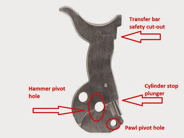
The hammer, you can see the cut-out where the transfer bar fits. The transfer bar replaces the missing metal, allowing contact with the firing pin, when the trigger is not pulled back the transfer bar will not be in the up position and the hammer cannot make contact with the firing pin.
Also in the picture: the pivot hole and cylinder stop plunger the pawl pivot
The picture below shows the old model hammer, you can see the the surface is flat, no cut out
The Hammer Strut keeps the hammer spring in place and rides in a notch and the back of the hammer
The Cylinder Stop has multiple working surfaces. The back is where the hammer plunger rides, forcing the cylinder stop to disengage with the cylinder notches and then re-engage when the hammer is close to full cock.
The front part of the cylinder stop is pushed upward by this spring and plunger located in the grip frame
The cylinder has a hole in the center where the base pin acts as the axle, the ratchet gear on the rear is where the pawl engages the cylinder and forces it to turn
The pawl pivots off a hole in the bottom of the hammer, as the hammer moves rearward it forces the pawl up and towards the cylinder gear, turning the cylinder. It also prevents the cylinder from spinning backwards (on most models) and is responsible for the clicking noise you hear when you spin the cylinder.
The pawl is pushed forward by this spring & plunger which is held in place by the grip frame
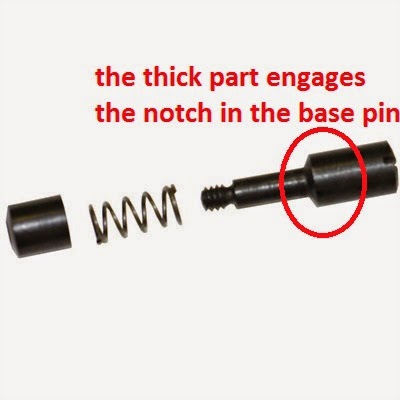
The Base Pin is held in by this latch made up of a screw, cap and spring, the thick part fills the notch in the base pin, when pushed sideways the thinner part allows the base pin to slide out.
Hammer pivot pin
Pivot lock grip screw, this is one of the grip screws that goes on the underside of the grip frame, you can put it on either side, as long as it matches the location of the groove on the hammer pivot pin, if you get it wrong, the screw will not go all the way in.
Trigger pivot pin
The gate spring serves multiple purposes. It maintains pressure on the gate (keeping it closed), it keeps the trigger pivot pin in place and it keeps the cylinder stop in place (this picture is inverted).
The grip frame showing the trigger spring pivot and perch and the main spring perch
Some of the pictures above were found freely on the world wide web and are used under the guidelines of Fair Use, per Title 17 of the U.S. Code. Where possible the source has been credited.
If you own the copyright to any of these images and wish them to be credited or removed, please contact me immediately.
references
Midway USA
GunsAmerica
Brownells
Chisel & Plane Workshop


